Guides / Design and Fit
Sizing a USB-C Cutout for the Cable Boot and the Daughterboard Behind It
November 3, 2026
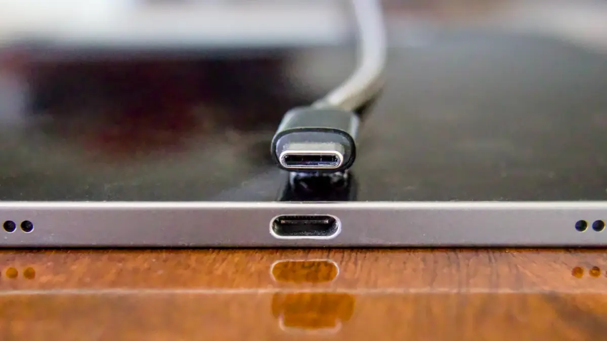
A keyboard case USB-C cutout has to clear the cable boot, not the socket. The socket opening is small and well defined. The moulded end of the plug that goes into it is larger, and it varies from cable to cable. A slot cut to the socket’s size will block thick cables, and the fault shows up as soon as a customer plugs in the cable they already own. This guide sets out the dimensions to work from, the position and depth questions that matter and what to put on the drawing.
The numbers come from Wikipedia for the socket, one vendor drawing for a plug overmold and the Unified Daughterboard project pages for two common board mounts. None of them is a standard for your cable or your board. Use them to frame the question, then measure your own parts.
Socket and boot are different sizes
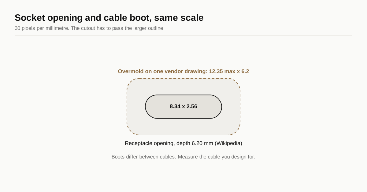
Wikipedia gives the USB-C receptacle opening as 8.34 mm wide by 2.56 mm high, with a depth of 6.20 mm. That is the hole in the connector shell, and it is the part of the problem that is fixed.
The plug has a metal tip that fits the opening and a moulded body, the boot or overmold, behind it. The boot is the larger part, and no single public figure applies to all cables. One vendor drawing for a USB-C adapter shows an overmold end view up to 12.35 mm wide and 6.2 mm high. The USB-IF publishes the connector specification, so check it if you need a formal plug outline. The vendor drawing used here describes one product, and other brands, braided cables and right-angle plugs can run bigger.
The photograph at the top shows the same thing in a real part. The plug’s boot is much taller and wider than the opening it enters. A cutout in a case wall must pass the boot, because the boot stops at the wall.
Choose the cable you design for
Decide which cables the cutout must accept before you set a size.
- The reference cable. Pick the thickest cable you want to support and measure the boot width and height with calipers.
- The supplied cable. If the group buy ships a cable, design for it and one fat third-party cable.
- Right-angle or braided plugs. Say whether they are in scope. A cutout that clears them is bigger and less neat.
The prototype guide lists a thick USB-C cable as a test item for a reason. Fit it before you release the run.
Position: three directions and a datum
A cutout position has three errors that add up: along the wall, up the wall and the depth of the wall.
- Along the wall. The socket sits at a fixed spot on the daughterboard or the PCB. Dimension the cutout from the same datum as the screw bosses, since the board sits on them.
- Up the wall. The socket’s height depends on the board and the standoff or boss under it. A few tenths of a millimetre up or down is a visible misalignment in a slot this small.
- Through the wall. The wall is a tunnel. The receptacle is 6.20 mm deep, and the plug must reach it, so a thick wall in front of it means a deeper cut and a longer tool reach. Counterbore or chamfer the outside if the wall is thick, and state the depth the plug must reach.
State which edge of the slot the tolerance applies to. The tolerance guide explains why position matters more than size on features like this.
The daughterboard mount
Many modern boards put the USB-C socket on a small daughterboard connected by a cable. Two Unified Daughterboard variants show how the mount shapes the cutout.
- The S1. The project page gives 40 mm by 9 mm, a board thickness of 1.6 mm and two M3 mounting points. It can be mounted either way up. The page says the large corner radii let a case be milled with a large inner radius.
- The C4. The CannonKeys page lists four M2 screws and a square board, and says it is backward compatible with boards that used the C3.
The number and size of the screws decide the bosses, and the board’s outline decides the pocket. The screw insert guide covers how small bosses and threads are cut. Draw the pocket and the slot together, on one datum, from the board’s published file.
A grounding detail applies here. The C3 repository says its top-left mounting hole is tied to power ground, so the metal chassis is grounded through it, and the C4 page lists single-path grounding to the keyboard case. Wikipedia states that the anodic layer is insulative. If the design depends on a screw boss for ground, tell the shop which faces must stay bare or be masked.
Machining notes for the slot
A slot like this is a small feature on a side wall, and a few points follow from that.
- Inside corners. A router cuts a rounded corner set by the tool radius. A slot with tight corners needs a smaller tool and more time. Give the corner radius you can accept on the drawing.
- Orientation. A cutout on a side wall may need its own setup on a three axis machine. The five axis versus three axis guide explains the cost, and the 65 percent case guide lists the USB cutout as a side feature.
- Edges. Break the outside edge so the plug does not catch on a sharp lip. Say whether the break is a chamfer or a radius and its size, as in the diamond cut edge guide.
- Deburr. A burr inside a small slot is hard to see and easy to feel. Ask for an inspection with a gauge cable.
Finish changes the size
Anodising adds a film that grows each surface by half its thickness, according to Wikipedia. It gives Type II coatings as 1.8 to 25 µm, so a slot wall can move in by roughly 0.9 to 12.5 µm on each side across that range. That is small against a boot, but it matters if the clearance is thin or the cutout is a tight fit around the socket. State whether the cutout dimension applies before or after the finish.
Checklist for the drawing
- Reference cable named, with its measured boot width and height
- Slot width, height and corner radius, with tolerance and the datum it is measured from
- Wall depth and any counterbore or chamfer on the outside
- Daughterboard or PCB model attached, with the bosses on the same datum
- Finish stated, and whether dimensions apply before or after it
- Faces that must stay bare for grounding, if any
- A test with the thickest cable at the prototype stage
The drawing callout reference shows how to word these and the CAD package guide lists what else to send. To compare shops on a drawing, send the files through the RFQ form. We match the request with up to 3 shops and reply within 24 business hours.
Sources
- Wikipedia, USB-C (receptacle opening 8.34 mm by 2.56 mm, depth 6.20 mm)
- L-COM, UAD043MF USB-C adapter drawing (overmold end view, 12.35 mm max by 6.2 mm)
- Unified Daughterboard, UDB-S project page (size, thickness, M3 mounts)
- Unified Daughterboard, C3 project page (ground path through the mounting hole)
- CannonKeys, Unified C4 daughterboard (4 x M2, commercial listing)
- Wikipedia, anodizing
The overmold figure comes from one vendor drawing and is directional. Measure your own cable before you set the slot.
Frequently asked questions
How big is a USB-C receptacle opening?
Wikipedia gives the USB-C receptacle opening as 8.34 mm by 2.56 mm, with a depth of 6.20 mm. That is the socket, not the cable end. The moulded boot on a plug is larger, and boot size varies between cables, so a cutout sized to the socket alone will block many cables.
How large should the cutout be for the cable boot?
Size it for the largest boot you want to accept. One vendor drawing of a USB-C adapter shows an overmold up to 12.35 mm wide and 6.2 mm high, and other cables differ. Pick your thickest reference cable, measure it, then add clearance for position error and finish build-up.
Does anodising change the size of a cutout?
Yes, slightly. Wikipedia says anodising grows each surface by half the film thickness, and it gives Type II films as 1.8 to 25 micrometres. A cutout that is tight on bare metal can close up after finishing, so state whether the dimension applies before or after the finish.
How do I fix a USB-C daughterboard in a case?
Follow the board's own mount pattern. The Unified S1 daughterboard uses two M3 mounting points on a board 40 mm by 9 mm and 1.6 mm thick, and the C4 uses four M2 screws. Boards differ, so draw the bosses from the board's file and put the cutout position on the same datum.
Need a quote for your case?
Send the files. We match you with up to 3 shops that machine keyboard cases and reply within 24 business hours.
Get matched with a keyboard case shop